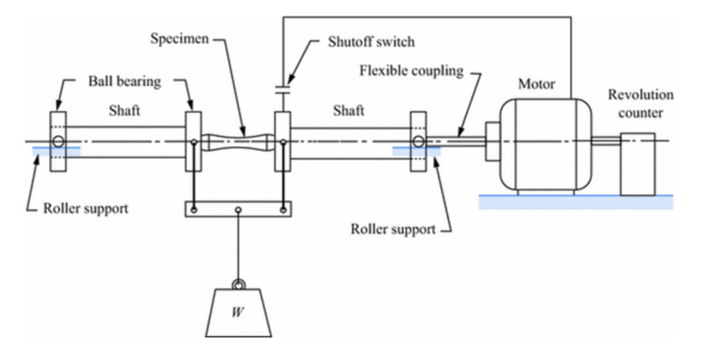
The determination of the fatigue resistance or fatigue life of desired metals is crucial for the progress of material selection and design. Hence, like other mechanical properties or failure mechanisms, fatigue properties can also be simulated by using specific devices. Standard test devices apply compressive and tensile stresses on the metal to simulate a fatigue cycle. The simulation of the fatigue cycle is maintained by the repeated utilization of the tensile and compressive loads. Moreover, to yield a reliable result from the test, test conditions (amount of stress applied, stress amplitude, and frequency) show similarities with the service conditions of the material that is tested.
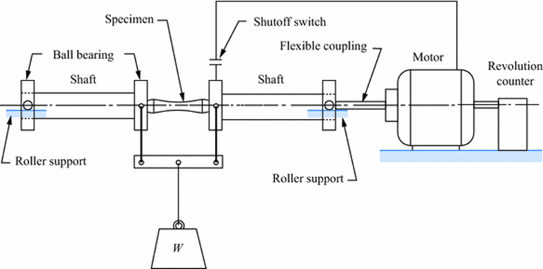
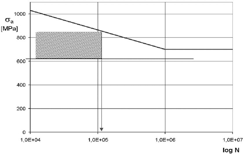
Tests for fatigue life determination is conducted at maximum stresses (generally) that are implemented as %66 of the tensile strength of the material. The stress cycles are applied to the specimen until the failure of the sample occurs. When the sudden fracture of the specimen is observed, the applied stress for the new pieces is lowered. For every new specimen, the applied stress level and fatigue cycles are counted and saved for analysis. Data from the experiment is used for drawing an S-N diagram. In the diagram, S refers to maximum applied stress or stress amplitude, and N refers to the number of cycles to failure. As a result of the S-N diagram, one can estimate the fatigue life of a specific metal under specific stress amplitudes. When the applied stress value is lowered, the number of cycles to failure increases. Therefore, under low-stress levels, the same material can resist a higher number of cycles. The S-N curve characteristics can be divided into two groups: the diagrams for ferrous alloys (and some titanium alloys) and diagrams for non-ferrous alloys. The shape and the curve of the diagram are different for both ferrous and non-ferrous alloys. In the S-N curve of the ferrous alloys, the curve becomes horizontal at some specific stress point. At this point, the number of cycles becomes relatively high when compared with the level of stress amplitudes. Thus, this horizontal zone of the curve is called as endurance limit or fatigue limit. The meaning of the fatigue limit is vital for the design considerations since the safety of the components can be ensured by calculating the endurance limit value for corresponding stress amplitude values. When the curve moves along a horizontal direction, below regions of the curve becomes safety zones for the metal. In other words, lower stresses than the stress value where the horizontal movement of the curve starts can be considered as the stresses that can never cause fatigue failure in the metal body. The importance of the endurance limit is substantially high for material design and selection. If the selected material is operated under the endurance limit, the possibility of the fatigue failures is minimized (according to the experimental results, under the endurance limit, there is no fatigue failure possibility for the ferrous alloys; however, the shape of the material must also be taken into account when the determination of fatigue life is done). The endurance limit for most of the steel grades is determined as in the range of %35-%60 of the yield strength. Over the endurance limit, the cycles to failure must be well-known for the safety of the material. One must calculate the number of cycles until the failure, so before the fracture of metal, the component can be replaced with a new one. Usually, the number of cycles are named as ‘low cycle’ and ‘high cycle’; also, the failure of the material is identified as ‘low cycle fatigue’ and ‘high cycle fatigue.’ For mid-carbon ordinary steel grades, cycles over 107 are called high cycle fatigue, and cycles below 104 are called low cycle fatigue. In contrast with the name of these terms, the strain rate of the materials under low cycles is higher than the strain rate of the materials under high cycles. The below S-N curve (Wöhler’s Diagram) represents the stress amplitude- cycle number relationship for 40 HM structural steel.
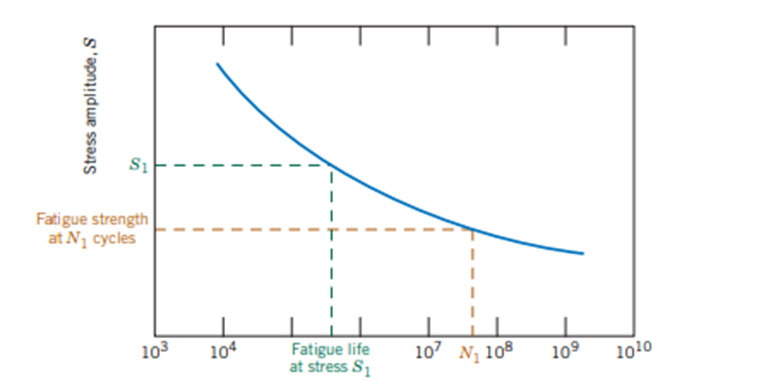
The stress-cycle diagram of non-ferrous alloys differs from the ferrous alloys, as stated before. In contrast with the ferrous alloys, the S-N curve of non-ferrous alloys doesn’t have an endurance limit or horizontal regime. Thus, as the number of cycles increases, the required stress amplitude or stress amount for fatigue failure decreases. In other words, as the number of cycles increases, the curve of the diagram goes downward. Furthermore, the possibility of a totally safe zone for the non-ferrous alloys is extremely low. The below Wöhler diagram represents the fatigue behavior of a non-ferrous alloy.
A detailed explanation of the progress of fatigue may be satisfactory for enthusiasts. The mechanism of fatigue has three elementary steps, which are crack initiation, crack propagation, and final failure. In the first steps of the fatigue, small cracks occur at the points where high-stress concentration exists. The propagation step is briefly the event where the crack propagation rate substantially increases. When the crack reaches the critical length, a sudden fracture of the material occurs. This stage is called the final failure step. The surface of the material is crucial for the progress of fatigue since the initiation of fatigue almost locates at the surface. The surface features can act as stress concentrating points for the material. The nucleation sites of the cracks may be sharp corners, dents, or scratches. Moreover, the microstructural defects of the material may behave as stress concentrating zones. For example, FeS inclusions in the steel may alter the fatigue progress because of the sharp-like shape of iron-sulfide. Another solid example can be given as the grey cast iron. The needle-like graphite structures act as stress concentrators and initiate fatigue. Moreover, the cyclic loads on the material may alter the motion of the slip bands and create intrusion and extrusion in the surface of the material. The movement of the slip bands and the emergence of the extrusion and intrusions are also stress concentrating zones, which means the initiation of the fatigue is most probably emerges in these points.
The propagation of the fatigue moves along in a horizontal direction. The fracture surface of the fatigue failures presents larger propagation areas when compared with the initiation zones. The shape and the traces of the propagation zone may include clues about the fracture type. Furthermore, the characterization of the propagation areas is called either ‘beachmarks’ or ‘striations.’ The beachmarks can be observed with naked eyes. The shape of the so-called beachmarks is observed as back-to-back rings or successive curves. Usually, these traces are examined at the parts that are not fully worked. For example, as a result of the fatigue failure of a machine that works six hours per day presents these beachmarks. In contrast with the beachmarks, striations are microscopic traces and can only be observed using electron microscopes. Unlıke the shape of beachmarks, striations are examined in linear forms. The below figure represents the beachmark traces on a fatigue fracture surface.
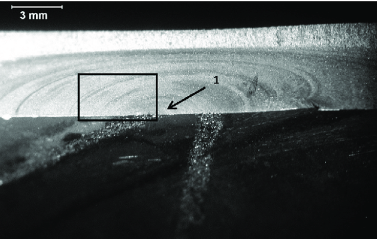
For further information please read: What Is Metal Fatigue? – An Overview
Read More: Altering the Fatigue Properties of Metals
References
- ARAUJO, J., SUSMEL, L., TAYLOR, D., FERRO, J., & MAMIYA, E. (2007). On the use of the Theory of Critical Distances and the Modified Wöhler Curve Method to estimate fretting fatigue strength of cylindrical contacts. International Journal of Fatigue, 29(1), 95–107. doi:10.1016/j.ijfatigue.2006.02.041
- Yildirim, H. C., & Marquis, G. B. (2012). Fatigue strength improvement factors for high strength steel welded joints treated by high frequency mechanical impact. International Journal of Fatigue, 44, 168–176. doi:10.1016/j.ijfatigue.2012.05.002
- Milella, P. (2013). Fatigue and Corrosion in Metals (1st ed.). Milano: Springer.
- Callister, W. (2001). Fundamentals of materials science and engineering (9th ed., pp.271,275). New York: Wiley.
- Nascimento, M. (2001). Effects of surface treatments on the fatigue strength of AISI 4340 aeronautical steel. International Journal of Fatigue, 23(7), 607–618. doi:10.1016/s0142-1123(01)00015-9

