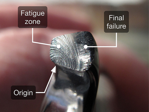
The importance of mechanical failure is evident for everyone related to engineering issues and components. Hence, the reasons for mechanical failure are clearly vital for those who are in search of better materials and engineering products. One of the most critical failure reasons of the materials is called ‘fatigue.’ According to the statistics, over 90% of mechanical failures caused because of metal fatigue. A brief definition of fatigue can be made as the piecemeal degradation and final failure of the materials under cyclic loads. The amount of the load can differ from the tensile strength of the material since the applied load on the material is usually dynamic. In other words, lower cyclic stresses than the tensile strength of the material may cause crack initiation and crack propagation in the material. The damages of the fatigue are substantially risky for the materials. Actually, among the five general failure mechanisms (ductile fracture, cleavage or brittle fracture, fatigue, creep, and corrosion), fatigue is the second most dangerous mechanism (the first one is considered as corrosion). Hence, satisfactory knowledge of fatigue is necessary for understanding the failure mechanisms. The nature of the fatigue fails is commonly considered as an initiation from the surface of the material and propagation with the help of cyclic loads. The initiation and propagation of cracks end with the final fracture of the material (metal). Fatigue failures are triggered by plastic flows on the surface of the material. Therefore, the source of the failures is called the ‘fatigue embryo’ that starts the whole failure. However, one must be cautious about the characteristic of fatigue failures. The nature of the fatigue failures can be identified as brittle even if the material is ductile. Moreover, the rate of plastic flow at the very beginning of the initiation only covers a small fracture. Total fracture behavior of fatigue is considered brittle since the final fracture suddenly occurs at the metal body. Fatigue embryos are generally observed on surfaces at specific crystal directions. However, initial submicroscopic cracks may end with the failure of the whole body. In the grain of the material, these submicroscopic cracks are transformed into micro-cracks by the action of the cyclic loads. The micro-cracks transform into macro-cracks and propagates along the grain boundary of the material. Thus, one must observe the surface quality of the desired material to prevent possible fatigue failures. As mentioned below, fatigue embryos emerge on the surface of the material, and surface quality directly affects the initiation of the fatigue. Materials with high surface roughness act as stress concentrators and ease the initiation of fatigue. The below figure shows the failure of a component because of fatigue loads.
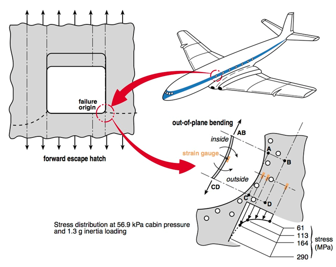
The importance of fatigue failures can be seen in historical disasters. As mentioned before, a considerable fraction of mechanical failures caused because of metal fatigue. Since the motion of the engineering products is maintained by the automatic systems (car engines, turbo engines, etc.), the repeated loads on the mechanical parts are inevitable. Hence, if the body of the engineering product contains surface discontinuities or stress concentrating points (sharp edges etc.), failure of the metal body is inevitable too. If the crack length in the body of the metal excesses the safety limits, under some specific cycles of the applied load, the crack propagates and suddenly fails the body. Engineering history has witnessed many accidents that were caused by fatigue of the metallic materials. A well-known accident can be mentioned as the failure of two De Havilland Comet passenger jets. The embryo of the fatigue was detected on the sharp corners of a window of the airplane. The sharp edge shape of the windows was caused just because of the square design. A small crack initiated on the sharp corner of the window and propagated. The observation on the crack propagation couldn’t have done by the experts before the flights. The reason for that was the material of the plane body. During the production of the jet airplane, designers decided to use 7000 series of aluminum for the body of the plane. However, the brittle nature of the 7000 series led to the catastrophic disaster since any or low plastic deformation occurred during the crack initiation. Brittle 7000 series aluminum leads to the sudden fracture of the body. The below figure shows the reason for the Comet Calamity.
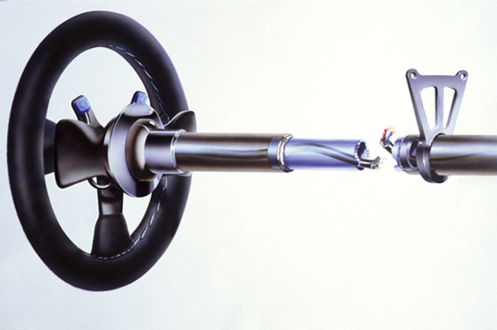
Another shocking disaster occurred in 1994 during the San Marino Grand-Prix. Worldwide known Formula-1 pilot Ayrton Senna crashed his car into the barriers. When the examination of the accident was done by the experts, it was clear that fatigue was the criminal of the catastrophe. Senna felt a little bit awkward while grabbing the steering wheel. Thus, the engineering team welded an inner tube to the steering to expand it. Nevertheless, during the attachment of the inner tube, microcracks formed on the steering. Experts claimed that, during the drive, cracks propagated, and the steering has failed. As a result of this, Senna couldn’t control the car and crashed into the concrete barriers. This catastrophe has changed many of the design considerations of the Formula-1 racing cars. The below figure shows the failure of the steering wheel that leads to the disaster.
The number of accidents due to fatigue failures is several in numbers. Thus, the mechanism of fatigue must be well-understood for having solid knowledge on failure mechanisms. Before starting the mechanism of the fatigue (crack initiation, crack propagation, and final fracture), it may be beneficial to discuss the term ‘cyclic loads.’ As mentioned before, cyclic loads that are applied on a material may result in the failure of the material even if the loads are lower than the tensile stresses. The cyclic loads can be defined as the continuous stresses that are applied to the material in opposite directions (not always, but in general). Therefore, the tensile and compressive loads generally form fatigue cracks on the body of metal. The repeated tensile and compressive loads are represented as sinusoidal curves in stress diagrams. Commonly, the applied stresses are classified into three categories, which are axial (tensile and compressive), torsional, and flexural stresses. The shape of the stress-time diagrams may vary; however, there must be positive and negative stress values for defining the fatigue phenomenon. The negative stress value can be described as the stress values that are lower than the maximum stress of the cycle. Hence, the sign of the stress is not important; the load cycle must contain higher and lower stress values, repeatedly. At that point, certain terms about the fatigue cycle must be well-defined to yield proper learning. The formulas of the mean stress, stress range, stress amplitude, and stress ratio can be seen below;
- The mean stress term is defined as the average of minimum and maximum stresses on a stress period or cycle.
σm = (σmax + σmin) / 2
- The term ‘stress range’ can be described as the difference between the maximum stress and minimum stress
σr = σmax -σmin
- The amplitude of stress is the half of stress range and calculated as;
σa = (σmax – σmin) / 2
- A final term on fatigue is defined as the stress ratio, which is the rate of the minimum and maximum stresses.
R = σmin / σmax
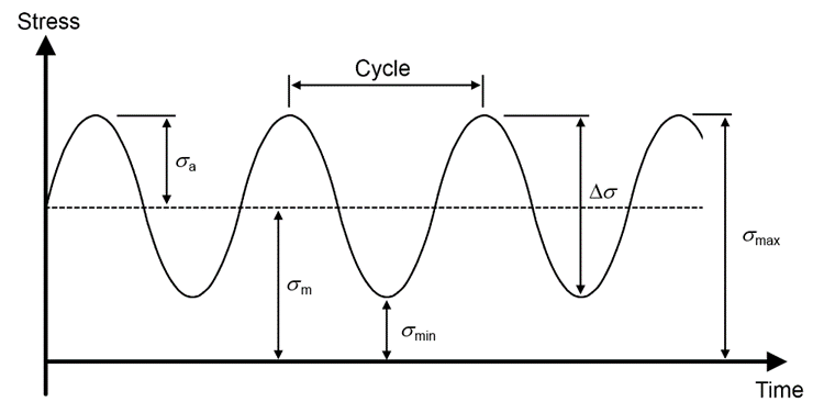
Most of the stress-time diagrams show reversed-stress cycles where the maximum and minimum stresses are equal, and the stress amplitude of every process is similar to each other. However, the symmetry between maximum and minimum pressures may vary. In addition to that, the frequency of the cycles may also differ from each other. The repeat of the loads in different values is essential for fatigue. The below diagram shows stress-time cycles with different amplitudes and frequencies.
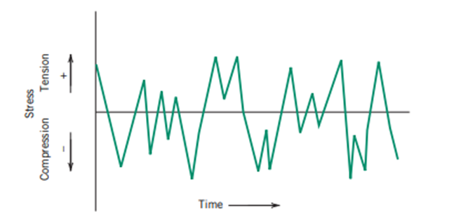
In brief, repeated loads on metals lead to fatigue failures. The characteristics of fatigue are vital since fatigue has some distinctive properties when compared with the other failure mechanisms. Some characteristics of fatigue can be listed as below;
- For a load cycle, the combination or repetition of compressive and tensile forces is not necessary for the initiation of the fatigue. Stresses that are varying in numbers can create fatigue in the metal body. For example, only positive or negative signed loads can cause fatigue if the amount of the stresses differs from each other
- Most of the fatigue failures show little or low plastic deformation. Hence the shape change of the fractured body is minimum when compared with the ductile fractures.
- Fatigue-resistance of materials is related to several factors. These factors can be exemplified as; surface quality, the microstructure of the metal, operation temperature, residual stresses, etc.
- The yield strength of the material can be misleading when considering the fatigue life of the materials. Materials with high yield strength perform high fatigue-resistance. However, the material can fail under cyclic loads lower than the yield strength value of the material.
- Cracks that are both in micro and macro levels may trigger the fatigue initiation. Moreover, the design of the components (for example, Comet accident) directly affects the fatigue property of the materials since the shape of the design may act as a stress concentrator.
- The surface finish of the materials is extremely important in the manner of fatigue-resistance. A material with a good-surface finish shows higher fatigue resistance when compared with the same material with a fair surface finish
- Since the surface quality of the material affects the fatigue resistance, the hardness of the surface also contributes to the fatigue life of the same material. Thus, hard surfaces prevent the initiation of cracks and hinder fatigue failures.
Read more: Metal Fatigue – Wöhler Plot and Mechanisms
References
- FATIGUE PHYSICS | Fatigue Life LLC. (2020). Retrieved November 2020, from https://fatigue-life.com/fatigue-physics/
- Callister, W. (2001). Fundamentals of materials science and engineering (9th ed., pp. 271,275). New York: Wiley.
- Milella, P. (2013). Fatigue and Corrosion in Metals (1st ed.). Milano: Springer.
- Bhaumik, S. ., Rangaraju, R., Venkataswamy, M. ., Bhaskaran, T. ., & Parameswara, M. . (2002). Fatigue fracture of crankshaft of an aircraft engine. Engineering Failure Analysis, 9(3), 255–263. doi:10.1016/s1350-6307(01)00022-x
- Tanaka, K., Nakai, Y. & Yamashita, M. Fatigue growth threshold of small cracks. Int J Fract 17, 519–533 (1981). https://doi.org/10.1007/BF00033345
- McDiarmid, D. L. (1991). A GENERAL CRITERION FOR HIGH CYCLE MULTIAXIAL FATIGUE FAILURE. Fatigue & Fracture of Engineering Materials and Structures, 14(4), 429–453. doi:10.1111/j.1460-2695.1991.tb00673.x

