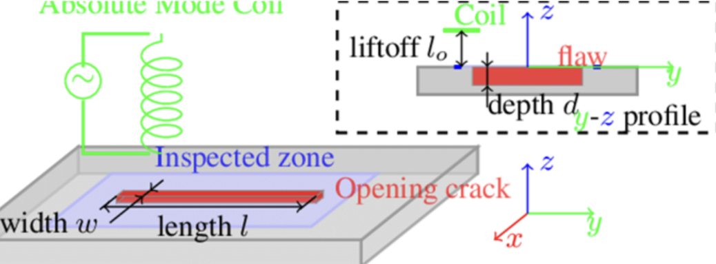
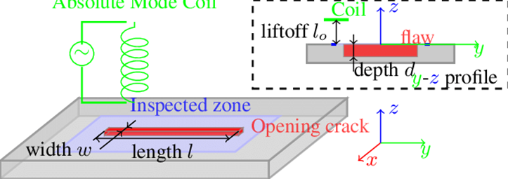
The detection of the defects on the surface or inner body of the materials can be maintained by implementing various methods. The non destructive test methods are several in numbers, which depends on the scope of the inspection. In addition to that, the condition of the defect in the investigated material may decide the required non-destructive technique since the examination methods directly vary on the location of the defect. Some methods can only be used for inner-body voids, whereas some techniques can be utilized for surface or near-surface cracks. The aim of the process must be decided well before the non-destructive inspection.
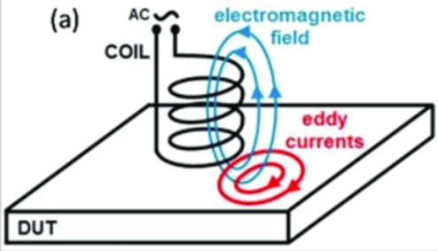
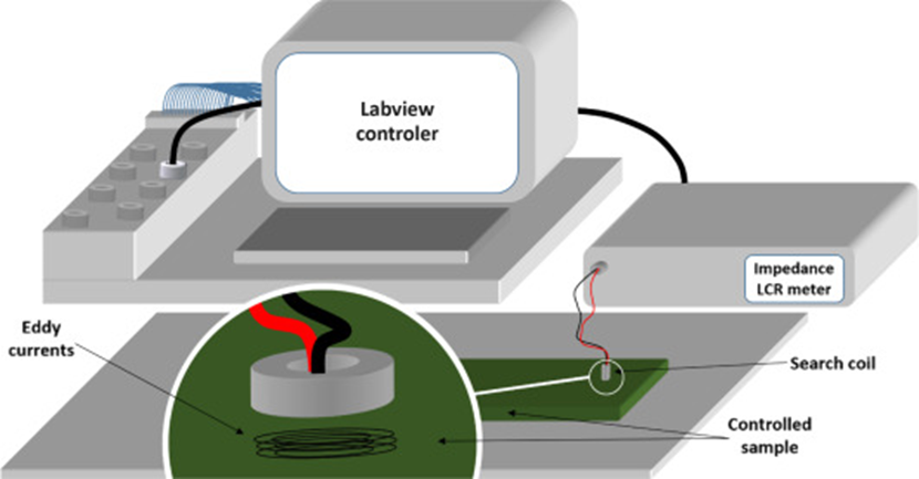
One of the most essential techniques that are widely used for non-destructive inspection is the eddy current testing. Eddy current testing can perform several identifications. The coating and dye thickness of materials is mostly estimated by using eddy current methods. Moreover, crack, and flaw inspection of related materials and examination of the material’s heat treatment conditions can be performed using eddy current testing. The importance of the magnetic fields and electromagnetism is apparent for non-destructive inspection methods. Similar to the magnetic particle inspection, eddy current testing also governs electromagnetism as the primary working principle. The theory of the eddy current testing is based on the changing magnetic fields. A circular wire or coil is used for the inspection. An alternating current is passed through the coil where magnetic fields occur just because of the current flow. The primary coil is kept near to the material that is desired to be inspected. The magnetic fields in the primary coil generate ‘eddy currents’ in the material. When the conditions of the inspected surface change, generated eddy currents on the surface change too. The deviations in the eddy currents are observed via using a receiver coil. Furthermore, the variations in the eddy currents can also be inspected according to the changes in the primary coil’s alternative current. The reason for the alternative current change may be sourced from numerous parameters. If the inspected material contains flaws, cracks, or any other discontinuities, the electrical conductivity feature of the material can be stated as heterogeneous. In brief, the discontinuities in the body change the magnetic permeability and electrical conductivity. Hence, produced eddy currents also deviate, which can be monitored by controlling the changes in the alternating current. A schematic of the eddy current generation can be seen in the below figure.
As mentioned in previous non-destructive test methods, the eddy current method also has advantages and disadvantages depending on the application and material. According to the location of the defects, the eddy current technique can be a quick and straightforward way for the inspection. However, the penetration depth of the eddy current method is vital for proper inspections since excess of the detection range may result in erroneous results. The common advantages and limitations of the process are written below articles.
Advantages of the eddy current testing;
- The eddy current method can detect defects that present even in complex parts. Hence geometry of the investigated part is not a constraint for the process
- The results of the inspection can rapidly be imported. The eddy current testing is considered as a fast process since the inspector can observe the data simultaneously
- The eddy current method is mostly free from the conditions of the surface. Pre-cleaning of the surface is not important for the eddy current testing as in the dye penetrant or magnetic particle inspections. Moreover, during the utilization of the method, there is no need for any substance for defect inspection. In dye penetrant testing, penetrant and developer liquids are required, or in magnetic particle testing, dry or liquid particles are necessary for the examination.
- Utilization of the eddy currents for inspection enables the detection of surface or near-surface defects. The method is susceptible to cracks down to 0.5 mm.
- The layered structure of the material that will be tested is not a limitation for the eddy current testing. In addition to that, nonconductive dyes or coatings are not required to be removed during the eddy current inspection.
- The eddy current method can also be used to investigate the electrical conductivity of materials.
- Inspections can be automated for duplicate production. For example, during the production of the boiler tubes, an automated eddy current method is utilized.
Disadvantages/Limitations of the Eddy Current Testing
- The conductivity of the investigated material is a limitation for the eddy current testing. The test piece for eddy current method must be a conductive material
- The eddy current inspection has limited sensitivity. The depth of penetration in the existing eddy applications is a limitation for the inspectors
- If the crack or flaw is parallel to the workpiece’s surface, the eddy current method cannot determine these types of defects. Hence, the direction of the flaw is vital for the eddy current applications
- Eddy current method has a high susceptibility for differentiation in magnetic permeability. This high sensitivity of the technique limits the application of the process for certain cases. Inspection of weld seams and neighboring zones in ferromagnetic materials is challenging for eddy current testing. However, with the development of new eddy current test designs (probes and detectors), an inspection of these kinds of welds are available
A wide range of application areas is available for the eddy current testing since most of the engineering materials have surface or near-surface cracks. Most of them are electrically conductive. However, a listing of the application areas can be useful for a better understanding of the eddy current methods. The common application areas of the eddy current testing are explained in the below articles.
Inspection of the welded zones: The heat-affected zones and weld beads are inspected with eddy current devices for detecting the cracks. In addition to that, ultrasonic NDT devices are also used for inspection.
Surface investigation: Metal components, especially machinery parts, are examined with the help of the eddy currents. Surface investigations of the metal components are vital for most engineering applications. Stop pins of the aircraft are inspected by using eddy currents
Corrosion inspection: Corrosion is one of the most common failures for engineering parts. Eddy currents can be used for the detection of the corrosion zones of thin metal planes. Inner corrosion damages can be easily detected with the current method. Aluminum aircraft bodies are controlled frequently for possible corrosion zones. The layered structure of the body may hinder the detection of the deeper layers. The top layer of the aluminum body can be inspected by using ultrasonic devices; however, deeper layers can be detected by using eddy currents.
Conductivity determination: The conductivity rate of the metals can be detected by using eddy current methods. The conductivity test also gives clues about the heat treatment condition of the metal part.
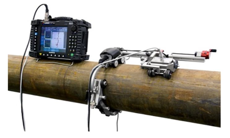
Inspection of piping elements: Eddy current testing allows inspectors to investigate the inner and outside cracks of the piping elements. Moreover, the changes in the thickness of the pipes can be detected by using eddy currents. Inspection can be done either during the fabrication or in the applications field. One advantage of the eddy current method can be mentioned as the quickness of the technique. Long pipelines for several applications can be inspected by using this quick method.
The detailed working mechanism of eddy current inspection method
The electromagnetic theory of the eddy current method was mentioned above. A wire coil or circular coil is used for generating magnetic field lines. When an alternating current flows through the wire coil, an oscillating magnetic field exists. The distance between the magnetic field and the inspected material is vital for the progress of the testing. If the wire coil is approached to the material that will be inspected, a secondary magnetic field occurs. The direction of the secondary magnetic field lines is parallel to that of the initial magnetic fields. At the same time, a circular electric field also occurs at the tangent of the secondary magnetic field lines. These circular loops are called ‘eddy currents’. The secondary magnetic field can also be defined as the magnetic field of the eddy currents. The secondary generated magnetic field interacts with the primary magnetic field of the wire coil. The inspection of the defects on the material can be detected by observing the variations of these magnetic fields. When the material preserves any discontinuity or thickness change on its surface or near-surface regions, the created eddy current’s amplitude and pattern changes. Changes in the amplitude of the eddy currents directly affect the secondary and primary magnetic fields. The change of the primary magnetic field also changes the impedance of the wire coil. The eddy current equipment observes and plots the variations of the impedance amplitude and phase angle. The variations of impedance amplitude and phase angle can be characterized by an expert who observes the eddy current device’s plot. The characterization of the differentiations is used for the inspection of surface and near-surface cracks and flaws.
The penetration depth of the eddy current testing is substantially important for the investigation process since eddy current devices can only detect discontinuities down to some degree. Usually, the density of the generated eddy currents is highest for the regions that are nearest to the surface of the investigated material. Hence, the accuracy of the eddy current testing is highest for surface and near-surface defects. A standard of the penetration depth is determined about 0.37 of the current density. This means current densities higher than 0.37 can be useful for eddy current inspections. The current density and the depth of penetration are calculated according to the conductivity and magnetic permeability of the inspected material. Moreover, the test frequency is another parameter for the depth of penetration calculations. These parameters are both effective on the accuracy of the test results. The conductivity and magnetic permeability of the material, the frequency of the alternating current, and the shape of the solenoid (wire coil) are both effective on penetration rate. The rate of penetration directly affects the resolution of the test since the eddy current density rate is the primary factor for accuracy.
The arrangement of the test parameters is crucial for the eddy current testing since the workpiece that will be tested may contain unique features. Not only the unique features but also the defect’s location and material’s thickness also affect the test parameters. The conductivity of the material is considered as a parameter for the eddy current testing. Materials with high electrical conductivities perform accurate results for surface defects; however, increasing the conductivity of the material decreases the depth of penetration. Moreover, the frequency of the alternative current also increases the resolution of the near-surface flaws but reduces the penetration depth of the probe. In contrast with that, lower alternative current frequencies enhance the penetration rate. Sizing of the selected coil is also crucial for the inspection. Larger-sized coils can scan large volumes in the material with deeper magnetic fields; however, small coils are commonly used for the detection of small flaws or cracks.
For further information please read: Non-Destructive Test Methods & Non-Destructive Test Methods 2
References
- García-Martín, J., Gómez-Gil, J., & Vázquez-Sánchez, E. (2011). Non-Destructive Techniques Based on Eddy Current Testing. Sensors, 11(3), 2525–2565. doi:10.3390/s110302525
- AbdAlla, A. N., Faraj, M. A., Samsuri, F., Rifai, D., Ali, K., & Al-Douri, Y. (2018). Challenges in improving the performance of eddy current testing: Review. Measurement and Control, 002029401880138. doi:10.1177/0020294018801382
- Helifa, B., Oulhadj, A., Benbelghit, A., Lefkaier, I. K., Boubenider, F., & Boutassouna, D. (2006). Detection and measurement of surface cracks in ferromagnetic materials using eddy current testing. NDT & E International, 39(5), 384–390. doi:10.1016/j.ndteint.2005.11.004
- Takahashi, Y., Urayama, R., Uchimoto, T., Takagi, T., Naganuma, H., Sugawara, K., & Sasaki, Y. (2012). Thickness evaluation of thermal spraying on boiler tubes by eddy current testing. International Journal of Applied Electromagnetics and Mechanics, 39(1-4), 419–425. doi:10.3233/jae-2012-1491
- Hur, D. H., Choi, M. S., Lee, D. H., Kim, S. J., & Han, J. H. (2010). A case study on detection and sizing of defects in steam generator tubes using eddy current testing. Nuclear Engineering and Design, 240(1), 204–208. doi:10.1016/j.nucengdes.2009.10.006
- Eddy Current Testing – A Definitive Guide. (2021). Retrieved 10 Jan 2021, from https://www.twi-global.com/technical-knowledge/job-knowledge/eddy-current-testing-123
- Eddy Current Testing (ECT) | Eddyfi. (2021). Retrieved 10 Jan 2021, from https://www.eddyfi.com/en/technology/eddy-current-testing-ect

