In today’s world, pipelines are very common for almost every application that transports any liquid or gaseous substance. These liquid or gaseous substances flow in the pipe system with different pressures and temperatures. Therefore, pipeline systems are suffered from excess stresses that are produced by pressure and temperature. Thus, the pipeline system must be designed and produced in a way that can handle the induced stresses during the transportation of liquid or gaseous substances. Some facilities (power plants, petroleum refineries, etc.) require long and complicated pipeline systems. Moreover, these types of facilities handle problems because of the limited working space. The pipeline system must be produced and mounted away from the facility site. These complex facilities use pipe spools with different measurements and various components. Pipe spools are the prefabricated segments that include pipes, flanges, and fittings. Pipe fittings are the components that connect the complex pipe network. Moreover, pipe fittings change the piping systems’ either sizes or dimensions. There are various types of fitting components but they can be briefly divided into three groups which are elbows tees and flanges.
Components of Fitting Systems
- Elbows
Elbows are generally used for a change in the direction of the flow. Common elbow systems can change the angle of the flow at 180°, 90° or 45°. The 180° elbow system is also called a ‘return bend’. The elbow systems can be classified into two groups which are butt weld elbows and reducing elbows. Butt-welded elbows are the most common and desired components. The whole butt weld system must be produced with the beveled ends. The 90° butt welded elbows are produced to make a perpendicular angle in every direction. They can be supplied as short and long radius ones. The desired fixation and the correct centering between the components can be maintained via using a truly calculated radius. Therefore the selected radius of the elbow can be very important. The other type of elbows is reducing elbows. In this type of elbows, the dimension of the center-line radius equals to the half of the nominal size of the larger end. Reducing elbows, again, maintain a 90° flow change in the pipeline system. Moreover, a 180°flow change can also be maintained by using a specific type of reducing elbow that is called ‘return bends.
- Tees
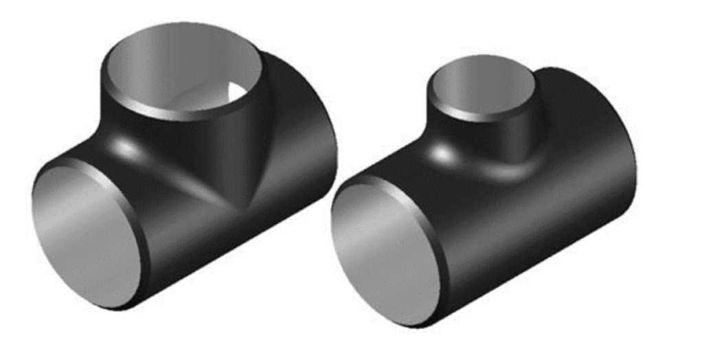
The tees are also used for the change of the flow angle and distribution of the flowing matter either into one or more channels. Tees can be divided into two main groups which are the butt welded tees and the socket welded tees. The butt welded tees are utilized to perform a perpendicular distribution of the flow. They make 90° branches with the connection of the pipeline and distribute the coming matter from the mainline. The butt welded tees can maintain a straight flow or reducing flow which depends on the ordered pipeline system. The reducing branches (reducing tees) make a perpendicular connection with the mainline. The radiuses of the tees are usually smaller than the main flow line. The radiuses of the straight tees are produced in a way that has similar radiuses with the main flow line. The socket welded tees also make a perpendicular angle between the connected lines. They used for high-pressure applications. In opposition to the butt welded tees, the socket welded tees are utilized in applications where the radius of the pipes are generally smaller. The socket welded tees do not require the beveling process before welding. Therefore, these types of tees are favorable in some applications where branch ends must be kept in the same form before and after the welding. The socket welded tees are manufactured due to the ASTM ASME B16.11 standards. These standards optimize and decide the proper pressure and temperature ratings, radiuses and required material for the production of the tees. Furthermore, the B16.11 standards are only allowable for carbon and alloy steels. The socket welded tees can be produced into three pressure categories which are; Class 3000, Class 6000 and Class 9000.

Figure 1. Straight and reducing tees. Retrieved from Butt-weld Fittings General – Tees and Crosses Straight and Reducing. (2020). 3 February 2020, http://www.wermac.org/fittings/buttweld_fittings_part3.html
- Flanges
Flanges are the components that work as a connector between main pipes, valves or pumps. The most prominent advantage of the flange usage easy the ease of cleaning and inspection of the area connected by the flanges. Flanges are usually produced by utilizing welding or screwing methods. Flange systems make a joint between different components. The joint is created by bolting two flanges to each other and sealing them by using various gaskets. Flanges are usually made of aluminum, bronze, brass or carbon steel. The most preferred material for general flange applications is the forged carbon steel. Moreover, flanges can be layered internally with different types of linings. Usually, flange material is selected as the same material with the pipe material. This material selection is conducted in order to prevent possible galvanic corrosion risks. The proper material selection for flanges is decided according to ASTM A-182 standards.
The specification of the flange types is done via the ASME B16.5 standards. Thus flanges are classified as; weld neck, slip-on, socket weld, lap-joint, threaded blind. The weld necked flanges are easy to recognize. A cylindrical bulge with a gradually increasing radius is connected to the main hollow part. The cylindrical bulge eases the use of flange in extreme conditions such as; elevated temperatures or high pressurized atmospheres. These flanges are welded to pipes or fittings by using butt-welding which enables a total fixation of the body. Slip-on flanges are also very common in use because of their low cost. They do not require excessive surface finishing as weld necked flanges. Therefore, the fixation of the slip-on flanges is easier. However, the strength of the slip-on flanges is two-third of the weld necked flanges, under internal stresses due to flow. Another disadvantage of the slip-on flanges is that it’s impossible to fix a flange to the elbow or fix a flange to the tee because the end surface of the slip-on fittings is not straight. The third flange group is the socket weld flanges. These flanges are utilized for small pipes that must yield high pressures. The strength of the socket weld flanges against internal stresses is equal to slip-on flanges. However, their fatigue strength is higher than the slip-on flanges. A major problem of the socket weld flanges is the corrosion risk. A gap between the flange and fitting or pipe must be maintained before the welding. Corrosive fluids or humidity can locate in these shelters. Thus, this solid-liquid interface may cause corrosion on the body. The lap-joint flanges have the nearly same shape as the socket weld flanges except for the weld gap. Thus, their use in applications that can cause corrosion is advantageous. Another flange type is the threaded flanges. The threaded flanges are very useful in specific applications since they do not require welding for fixation. Blind flanges are the final division of the flange classification. They are used as end-closers for the pipes valves or pumps. Since blind flanges are used as obstacles against the fluid flow, they are the highest stressed parts of the flange systems.

Figure 2. Most common flange types. Retrieved from Flanges General – Flange Types – Welding Neck or Weld Neck flanges, Slip-On flanges, Socket Weld flanges, Lap Joint flanges, Threaded flanges, and Blind flanges. (2020).3 February 2020, http://www.wermac.org/flanges/flanges_welding-neck_socket-weld_lap-joint_screwed_blind.html
Manufacturing of Pipe Spools
The production process of the pipe spools has several stages. All stages are implemented for particular aims and the array between the stages is voluminous. Therefore, the manufacturing steps can be divided into marking, cutting, fit-up, welding, and painting.
As a beginning of the manufacturing, all components must be marked in order to increase the monitorability of the materials. The marking work can be implemented due to the respective number of components. Moreover, all dimensions of the pipe spools must be marked on to themselves. The traces on the components must not contaminate the material otherwise traces can react with the material and this may cause deleterious problems.
The following procedure after the marking is the cutting step. The way of cutting differs for various materials. Thus, for carbon steels, the flame cutting method is utilized. Moreover, stainless steel components can be cut using a plasma arc cutting machine. If the plasma arc cutter is used some certain conditions must be maintained. The plasma arc cutter is utilized for large pipes (above 28 inches of nominal pipe size) and its use is also beneficial for cutting off branches. If possible, an internal case must be located into pipes or fittings, in order to protect them from the spatters which are created by the plasma arc cutter. After the cutting, and edge preparation must be maintained. The surface edges of the components must be even and the surface impurities must be removed. A beveling process is implemented for the edges of the parts. A grinding machine is employed for the beveling process. The type of grinding machines for beveling differs for stainless steel components and carbon steel components.
A fit-up and welding process must be applied after the edge finish of the parts. Therefore, for stainless steel and carbon steel pipe spools, parts can be located onto steel bases or wooden bases. Furthermore, any contact possibility between carbon steel and stainless steel must be minimized. The number of welds on a spool must be kept in a minimum count. The dimension of the spacing between circumferential welds and the center lines must not be larger than the four times the wall thickness of the pipe or fitting. After the main welds, tacks welds must be done precisely. All welds in the spools must be implemented according to proper Welding Procedure Specification (WPS). After the welding process is done, quality control of the components is performed by the specialists.

Figure 3. Pipe spool fabrication flow. Retrieved from Wang, P., Mohamed, Y., Abourizk, S., & Rawa, A. (2009). Flow Production of Pipe Spool Fabrication: Simulation to Support Implementation of Lean Technique. Journal Of Construction Engineering And Management, 135(10), 1027-1038. doi: 10.1061/(asce)co.1943-7862.0000068
The combined parts are heat treated with the aim of reducing the induced inner stresses. The heat treatment procedure is performed according to ASME B31.3 standards. Thereafter, the pipe spools must be painted for protection of the surfaces from any corrosion risk.
Are you also curious about the applications of pipe spools ?
Read another blog post about pipe spools: https://yenaengineering.nl/pipe-spool-applications/


