Steel is an iron-carbon (Fe-C) alloy that contains from 0.02% up to 2.1% C in weight. Fe-C alloys containing more than this percentage of carbon in weight are defined as cast iron in general terms. When the carbon content increases to 6.7%, an extremely brittle intermetallic compound called cementite (Fe3C) forms. The scope of this blog post will only cover the steel section of the Fe-C phase diagram.
Steel is an excellent material for various engineering applications by having a high melting temperature (around 1530˚C) and a wide range of mechanical properties. Besides the alloying elements, mechanical properties can also be modified suitably for different applications by adjusting the cooling rate of steel from its austenitic phase. There are several types of heat treatment methods applied on steels which will be comprehensively explained in this blog post.
What exactly is the heat treatment and why it is done?
Heat treatment is a thermal process applied to commercial metal products that involve heating and cooling cycles. In this process, thermal energy is used to alter the microstructure of the material. In this way, mechanical properties are improved. In some cases, the aim of heat treatment is not to improve the mechanical properties but just to soften the material for further processing, such as machining. Machinability is inversely related to the hardness of the material, therefore, machining a very brittle material can end up in the malfunctioning of working lathes due to excessive resistance against shaping.
It is easy to visualize as seen in the books and movies, a blacksmith holding a hot, glowing workpiece of steel, shaping it with a hammer. As he continues to shape the red-orange steel piece, it can be easily seen that the steel is shaped rather effortlessly when compared to a tough steel sword in normal conditions. It is nearly impossible to strain to harden a steel sword easily with a hammer. Explanation of this situation lies within the borders of a branch of solid-state physics, commonly known as materials science. When this Fe-C alloy named steel is heated up to a certain temperature area, it experiences a phase change and becomes austenite. This process is called austenitization. Austenite, having a face-centered cubic (FCC) structure, is the softest phase in the Fe-C phase equilibrium diagram. Therefore, the shaping of a steel sword becomes possible at elevated temperatures. This diagram is one of the most essential diagrams in metallurgical and materials science.
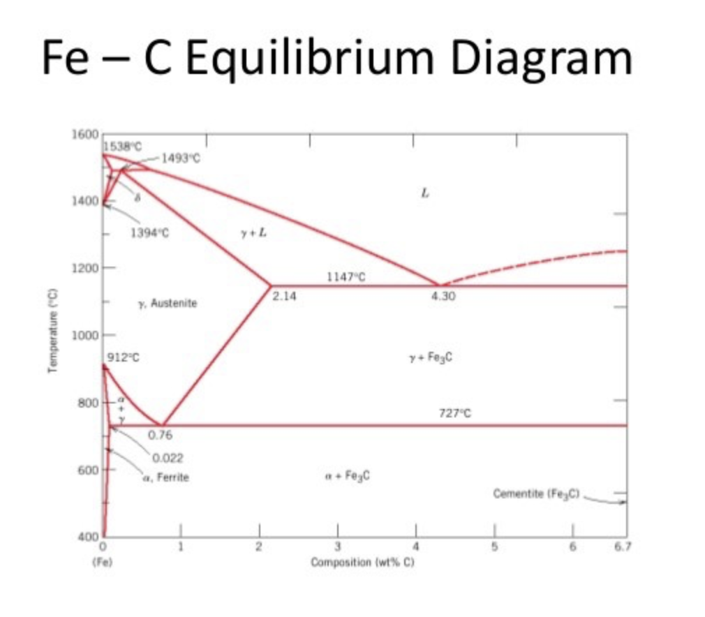
Fe-C Phase Equilibrium Diagram
In order to fully understand the theory of heat treatment, it is crucial to investigate the Fe-C phase diagram. This diagram helps metallurgists to determine the effects of chemical composition and temperature on phase formations.
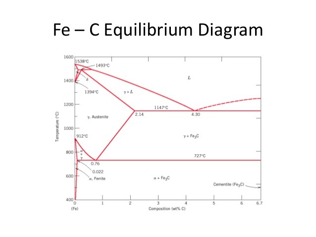
Figure 1: Fe-C Phase Equilibrium Diagram
As mentioned before, steel is defined as a Fe-C alloy containing up to 2.1% of carbon. After this percentage, this alloy is defined as cast iron. Steels are ductile materials when compared to cast irons. It can be deducted that increasing carbon content makes the material more brittle.
In terms of steelmaking, the most important part of this diagram is 0.76% C where the 100% pearlite structure is achieved. Pearlite is a lamellar microstructure that consists of repeating α (ferrite) and Fe3C (cementite) phases. This special structure makes the pearlitic steel very tough. It is also called eutectoidic steel.
When the carbon content of the steel is less than 0.76%, this steel is known as hypoeutectoidic steel. In hypoeutectoidic steels, the matrix of the microstructure is α and solid Fe3C particles precipitate on grain boundaries of ferrite.
If the carbon content exceeds 0.76%, steel becomes hypereutectoidic. In hypereutectoidic steels, ferrite particles precipitate on grain boundaries of Fe3C. When compared to hypoeutectoidic, hypereutectoidic steels are more brittle and low in ductility.
As it can be seen from the diagram, at 0.76% C and 727˚C eutectoidic reaction where austenite phase transforms into ferrite and cementite, takes place. The first phase precipitated is called proeutectoidic phase. For example, in the case of hypoeutectoidic steel formation, the proeutectoidic phase is ferrite.
Bainite and Martensite
Two more concepts should be mentioned in this part of the post that is related to the heat treatment of steels: Bainite and martensite. Bainite is a type of microstructure obtained by cooling the austenite phase down to a temperature where it is no longer stable enough to form pearlite. It is a non-lamellar aggregate of plate-like ferrite and cementite. Martensite, on the other hand, is not a structure. It is a phase, just like ferrite, austenite, delta iron (See the upper section of the diagram). However, the martensitic phase cannot be found on the Fe-C equilibrium phase diagram. This diagram only shows the equilibrium phases while the martensitic phase is not an equilibrium, but instead a metastable phase. It can only be obtained by rapid cooling, in other words, “quenching” of the austenite. This phase has the highest hardness and toughness values of them all, but in some cases when the martensitic transformation ending temperature is below room temperature, some of the austenite cannot transform and is locked inside the martensitic phase. This is called retained austenite and it is a problematic situation, which will be discussed in the next section where Time –Temperature-Transformation diagram is going to be explained.
TTT Diagrams: The Guidebook for Heat Treatment
Time-Temperature-Transformation diagram is a tool in which the different types of microstructures (pearlite, bainite) and phases (austenite, martensite) exist between the time (x-axis) and temperature (y-axis). Lines on the diagram indicate the starting and finishing line of the related phase of structure formation (See Figure 2).
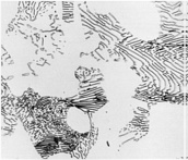
There are several different heat treatment practices in order to obtain indicated structures on this diagram. To begin with, annealing is one of the simplest heat treatments by increasing the temperature to austenitic phase (also called austenitizing) and furnace cooling to obtain coarse pearlite (Figure 3). Similar to this process, normalizing is done to achieve a fine pearlite structure by austenitizing and air cooling, respectfully. In normalizing, it can be easily seen that the cooling rate is higher.
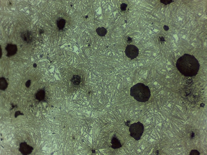
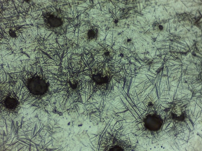
Austempering is another practice to obtain bainite structure (Figure 4) by austenitizing and quenching. The material is rapidly cooled by quenching until bainite forms. Depending on the cooling rate, feather-like upper bainite or acicular lower bainite can be formed. Finally, if one desires to form martensitic steel (Figure 5), quenching until Mfinish line should be done. Another way of achieving the martensite phase is an interrupted quenching method called martempering/marquenching. This method, it is aimed to dissipate the temperature uniformly throughout the material by giving it enough time. With this method, internal stresses which can cause some flaws such as crack quenching are eliminated. The major drawback of this method is that large materials cannot be heat treated in this way.
During the formation of martensite, some of the austenite may not be transformed completely and trapped inside martensite as a metastable phase, known as retained austenite. This problematic situation causes internal stresses and mechanical behavior is strongly affected. Thus, tempering should be done to transform the retained austenite to martensite. It is a simple process that involves heating up to a designated temperature and air cooling.
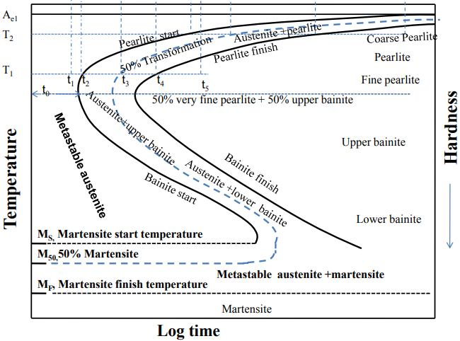
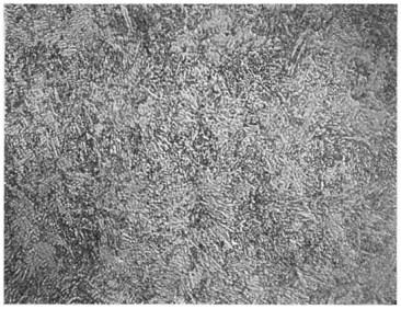
Figure 3: Coarse pearlite and ferrite (Baydogan M., 2018)
Figure 4: Upper bainite (left) and Lower Bainite (right) (Baydogan M., 2018)
Figure 5: Martensite (Baydogan M., 2018)

