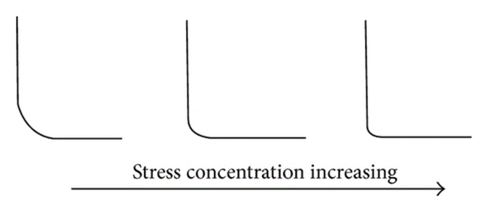
There are several parameters that substantially affect the fatigue life of metals. The design of the metal parts is an essential parameter that directly alters the fatigue strength. The design considerations on the engineering components must be adequately consulted before the use of the related parts. Most of the fatigue failures are sourced from the improper design of the metal bodies. During the design of the metal bodies, the shape of the component must be the first consideration for the designers. The importance of the component shape comes from the stress concentration phenomenon. As mentioned before, sharp edges on the metal bodies may act as stress concentrator points. Thus, crack initiation possibility on these sharp edges are higher than the blunt edges. In other words, sharp edges or corners may create a notch effect on the metal body, which is extremely undesirable for the fatigue life of the component. Furthermore, geometrical discontinuities on the body may act as stress concentrating points and ease the initiation of cracks. These discontinuities can be drilled holes or grooves or keyways. As the sharpness of the discontinuity increases, the stress concentration on these points also increases, and fatigue resistance of the material directly reduces. Hence, prevention of these faults during the design step of the engineering parts are strongly important for fatigue initiation. Sudden cross-sectional changes must be prevented, and sharp edges must be rounded to inhibit the stress concentration.
The design process of the products is maintained by taking into consideration the fatigue life of metal parts with respect to the projected service time of the same parts. Hence, some specific steps must be provided by the designers by considering all possibilities that may cause catastrophic disasters. Furthermore, three particular articles can be stated for ensuring the safety of the engineering parts. These articles can be listed as below;
- Design the material to ensure a fatigue safety zone. Material selection must be made carefully to provide a fatigue limit. Under the applied stress amplitude, the material must yield infinite fatigue life. Moreover, prevent sharp edges or sudden cross-sections on the metal. The material must perform the calculated cycles without any flaw or crack on the surface.
- If the economic considerations overcome the design parameters, determine the service time of the metal part. Replace the metal part with a new one when the initial metal completes the service time.
- Maintenance of the designed parts must be done periodically. The experts must inspect the metal part to detect the flaws or cracks. During the examination of the metal body, non-destructive testing techniques can be used. If cracks are seen on the metal, fatigue crack growth rate and critical crack length must be calculated, and an optimum service time for the metal part must be determined
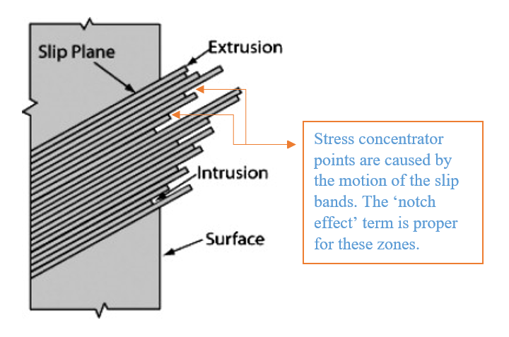
The design of the produced parts for enhancing fatigue life also covers the surface properties. However, most of the fatigue failures are directly related to the surface of the metals. Hence, a detailed examination and understanding of the surface quality are necessary for improving the fatigue properties. As mentioned before, cracks mostly originate on the surface of the metals. The mechanism of the cracks initiation is caused by the local plastic deformations. These plastic deformations occur on the surface of the metal. The reason for the plastic deformations is usually the motion of the slip bands. Hence, an introductory statement can be made as the motion of the sleep bands create a notch effect on the metal surfaces. At that point, maybe the meaning of the notch effect must be elaborated. As a reason for the slip, slip bands create extrusion and intrusions by sliding on each other. These extrusion and intrusions are mostly in micro-sizes. Hence, neighboring zones of these slip bands or extrusion and intrusions act as stress concentrating points. In these stress concentrating points, crack origination occurs and progresses. The progression of the crack emerges at an angle of 45° because of the dominant shear stresses. At this point, an extremely important phenomenon can be said as the surface hardness. The hardness property is directly related to the strength of the metals. One of the essential features of the strength in materials can be mentioned as the resistance against plastic deformation. Hence, since the hard materials are also considered high-strength materials, it’s possible to observe a strong resistance against plastic deformation. The possible motion of the slip bands is relatively low for the hard material when compared with the soft materials. Therefore, one couldn’t observe any significant extrusion or intrusion in the hard surfaces. The absence of the extrusions and intrusions also represents the low crack initiation possibility since there is no stress concentrator on the surface of the metal. The below figure illustrates the surface extrusions and intrusions.
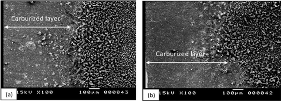
In brief, hard surfaces show remarkable fatigue resistance. Therefore, methods that increase surface hardness are used for enhancing the fatigue resistance of the metals. One of the most common ways of increasing hardness is case hardening. The case hardening method relies on the diffusion of the desired substance into the target metal. Usually, carbon or nitrogen is used for the case hardening. The metal body is placed into carbon or nitrogen-rich environment. At elevated temperatures, the diffusion of the carbon and nitrogen through the metal body is ensured. A typical case depth of 1 mm is provided during the application. The carbon or nitrogen-rich outer case is extremely hard when compared with the inner core of the metal body. Moreover, during the carburizing and nitriding processes (case hardening), desired compressive stresses can be observed in the regions which are close to the surface. These compressive stresses under the surface are vital for the fatigue resistance of the metal since they contribute to the fatigue strength. Since the diffusion is a time-dependent process, the case depth of the hardened layer may vary with the duration of the process. Below SEM micrograph shows the case hardened layers for two different operation durations.
Nitriding and carburizing covers a massive fraction of surface hardening methods. However, other processes such as induction hardening and flame hardening can be used for enhancing the fatigue life. Induction and flame hardening methods are mostly used for obtaining hard surfaces on steel components. In the flame hardening, the surface of the steel is heated by using a flame torch. The heated steel surface is quenched to obtain a martensitic structure at the steel surface. When the heated steel is quenched, the martensitic surface of the steel part exhibits ultimate hardness. In contrast with the flame hardening technique, the induction hardening method governs induction heating of the steel surface. Steel components are placed in a wire ring that creates induction and heats the surface of the steel. The quenching process of the induction bending is very similar to flame hardening, where the surface is rapidly cooled, and martensite is obtained. Nonetheless, both techniques have the same constraint, which is the carbon amount of steel components. In both processes, only medium and high carbon can be used since the aim of the methods is to yield a martensitic structure on the surface.
Although the discussed benefits of the above methods contribute to the fatigue life of the metals, some other phenomenon or practices may reduce the fatigue strength of the metal parts. During the heat treatment of the steel parts, some carbon atoms may diffuse from the surface to the outside of the steel. This is commonly called as decarburization of the steel. Thus, the reduction of the carbon on the steel surface directly reduces the surface hardness of the steel. Moreover, the normal hardness of the surface decreases. In addition to that, the reduction of carbon hinders the formation of martensite on the steel surface at the end of the heat treatment process. Otherwise, a soft coating on the metal surfaces might reduce the fatigue resistance of the metal because of the ductile layer on the surface (e.g., aluminum coatings). Electroplating processes may also decrease the fatigue life due to the alteration of the residual stresses and hardness of the surface.
The importance of residual stresses must be well understood when the increment of fatigue strength is examined. Residual stresses can be divided into two groups that are tensile residual stresses and compressive residual stresses. Usually, the tensile residual stresses are unwanted since they raise the propagation rate of the originated cracks. In contrast with the tensile residual stresses, the compressive residual stresses are desirable for the metal components. The residual compressive stresses beneath the surface of the metal increase the fatigue resistance. Both residual stresses arise when the elastic limit of the metal is exceeded; in other words, when the plastic deformation is initiated. The reasons for residual stresses are several in numbers, but the below articles represent a considerable fraction of the reasons;
- During the mechanical work of the metals, non-uniform plastic deformation may take place. These mechanical works can be; rolling, drawing, machining, shot peening, etc. The shot peening method is mostly used to create residual compressive stresses on the surface to reduce the fatigue rate.
- The phase changes of the metals may cause residual stresses
- Particular surface treating methods may also create residual stresses (CVD, PVD, etc.)
- Case hardening and nitriding methods can be mentioned as the processes that cause residual stresses.
- The temperature gradient during welding operations may create residual stresses. The hot weld seam and cold parent metal induce the residual tensile and compressive stresses.

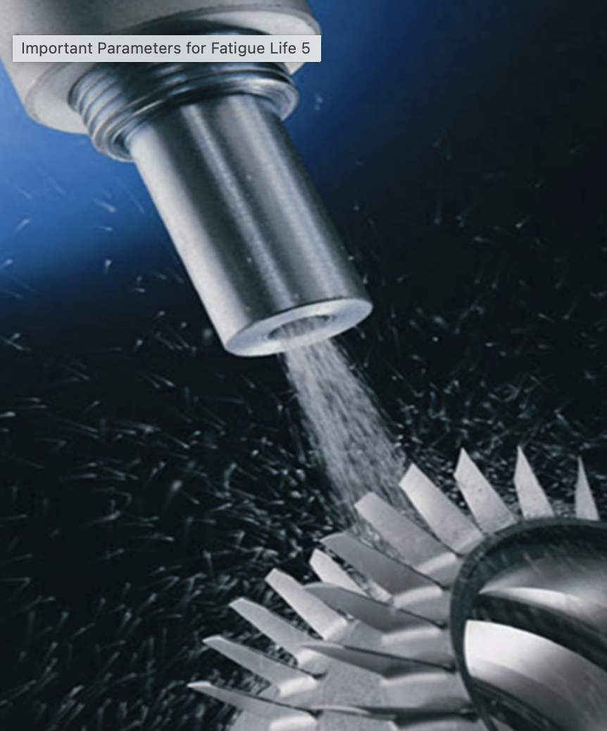
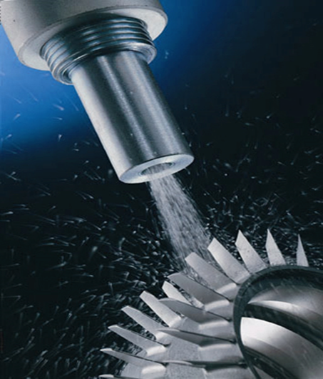
The shot peening technique can be mentioned as the most commonly used technique to enhance the residual stresses beneath the surface of the metals. In the shot peening practice, small particles are blasted through the surface of the target metal piece. The small and hard particles are sized in a diameter range of 0.08 to 0.8. The strike force of the particles to the surface of the metal alters the surface and near-surface regions. The most important effect of the shot peening process is the created compressive residual stresses at the near-surface zones. These compressive stresses are substantially effective for enhancing the fatigue resistance of the metal. The maximum compressive stress can be achieved by blasting the surface with half of the target metal’s yield strength. Besides that, the size of particles, duration of blasting, and hardness of particles may affect the strike strength of the particles. It should be noted that the shot peening method is mostly effective when dealing with high-cycle loads with low stresses. Another benefit of the shot peening method to the metal surface is the strain-hardening effect. Since the peening region suffers from plastic deformation, the strained surface is work-hardened. Hence, shot peening also contributes to the surface yield strength of the material, which is beneficial for fatigue resistance.
Environmental parameters must also be considered when the factors that affect fatigue is researched. Under corrosive environments, fatigue rates increase as a result of chemical attacks and cyclic loads. Such a combination of corrosive attacks and cyclic loads are called corrosive fatigue. For example, pitting corrosion on metal leads to the formation of small and deep holes. These holes or pits may act as stress concentrating points and accelerates the origination of cracks. Aside from corrosion, temperature change in the environment may alter the fatigue resistance. Under such conditions where excessive temperature changes occur, fatigue may be observed without any mechanical loads. The change of temperature creates thermal stress in the metal, and these stresses can cause fatigue in the metal. The amount of thermal stress can be determined by the below formulation;
σ= aEΔT
σ = Thermal Stress
a = Thermal expansion coefficient
E = Elastic Modulus
ΔT= Temperature Difference
Hence, the material selection must be adequately made by considering the thermal properties. Extreme temperature changes must be well calculated according to the service of the component.
For further information please read: Altering the Fatigue Properties of Metals
References
- Callister, W. (2001). Fundamentals of materials science and engineering (9th ed., pp.271,280). New York: Wiley
- Milella, P. (2013). Fatigue and Corrosion in Metals (1st ed.). Milano: Springer
- Hosford, W. (1993). The mechanics of crystals and textured polycrystals. New York: Oxford University Press.
- FATIGUE PHYSICS | Fatigue Life LLC. (2020). Retrieved December 2020, from https://fatigue-life.com/fatigue-physics/

