The failure of the materials is vital in the manners of both engineering and economy since the fractured part of a component may inhibit or prevent the working process. Hence, a detailed examination is usually done for the failured parts. A considerable fraction of the failures is sourced by the fatigue mechanisms. However, if the process is maintained under elevated temperatures, a new usual suspect emerges. This failure mechanism is called creep failure. A standard definition of creep can be made as the plastic deformation of materials under elevated temperatures and static loads.
Creep behavior is mostly essential for engineering applications that take place in high-temperature environments. Hence, the design of the metal parts must be done by considering the creep resistance. For example, turbine blades of jet engines usually suffer from creep as the inner atmosphere of the engine works at 800 to 1300°C. Furthermore, the centrifugal loads on the blades also contribute to the plastic flow of the material. Therefore, additional alloying elements are used to ensure an increment in the turbine blades’ creep resistance. Other high-temperature engineering applications can be exemplified as; nuclear reactors, boiler tubes, rocket engines, and steam turbines.
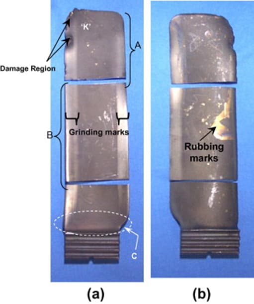
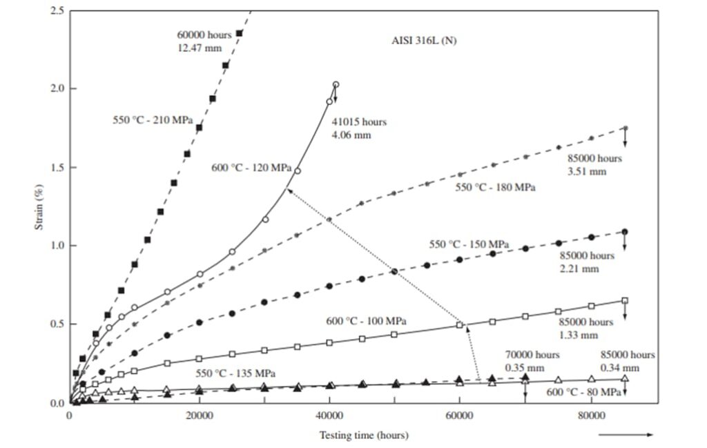
In the crystal structured materials (metals and ceramics), the critical creep temperature can be determined as the 0.4-0.5 of the melting temperature of related material. This critical temperature is crucial for the design considerations of the materials. When glasses and polymeric materials are taken into account, the glass transition temperature is decided as the critical point where large amounts of creep strain occur. However, some materials can suffer from creep even at room temperatures. These materials can be rubbery polymers or soft metals (e.g., lead). The critical temperatures for creep failures are vital for the selection of the proper materials during the design if the engineering components. To enhance the creep resistance of the materials, particular alloying elements are commonly used. At this point, nickel, chromium, and cobalt are widely used as the alloying elements to increase the engineering materials’ creep resistance. As stated before, jet engine turbine blades are produced via nickel superalloys (CMSX-4, CMSX-10, Inconel, etc.) and additional alloying elements (Rhenium, Ruthenium) that contribute to the creep resistance of the turbine blades. The plastic flow of the materials because of creep can vary for different temperatures and different tensile stresses. The change in the strain in accordance with varying temperatures can be seen in the below figure. When the model is examined, it’s evident that the plastic flow of the materials can occur at the stresses that are lower than the yield stress of the tested material. Likewise, fatigue failure the creep failure may start even at lower stresses than the yield stress. That’s why material design is extremely important for high-temperature applications. If the material selection is made by only considering the room temperatures or insignificant temperatures (temperatures that couldn’t contribute to the creep), catastrophes may emerge since the plastic flow’s initiation below the yield strength of the metal. The below figure represents the creep behavior of a 316L austenitic stainless steel, which is very commonly used for welding applications.
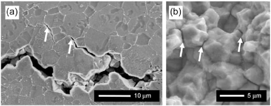
The mechanism of the creep failure is also crucial for enhancing the creep resistance of the metals. One must properly examine the fractured surface of the metal that is failed so far. Most of the examinations show, cracks occur on the grain boundaries of the failed metals. Hence, the fracture characteristics of the creep failures can be defined as intergranular for most cases. Moreover, the high-temperature environment where the metal part is operated may cause ductile type fracture. Hence, it’s clear that the creep failures are intergranular ductile fractures (for most failures). Since creep failure cracks are initiated on the grain boundaries of the relative metal, the absence of grain boundaries may become advantageous for high-temperature applications. Hence, the metal parts that are designed for high-temperature applications are produced by decreasing the number of grains. Most of the turbine blades are made by providing single-crystal structures where only one grain boundary presents. The below figure shows the intergranular fracture of a metal part that is suffered from creep.
The resistance against creep can be obtained by running particular creep tests for the desired metal parts. Usually, tensile tests are applied to understand the plastic flow and the strain rate of the material. However, the prediction that is evaluated by the tensile test cannot be used for the materials that are planned to be used in high-temperature applications. The strain rate that is determined at the end of the tensile test is proper for the applications that take place under room temperature conditions. At this point, the strain of the metal for applied stress will not change within time because of the low temperature of the environment. Nonetheless, if elevated temperatures are taken into account, the strain rate must be calculated for the exact operating temperature since the creep is the primary failure mechanism. Here, one-fourth of the materials melting temperature must be conducted during the tensile test to simulate the material’s behavior under elevated temperatures.
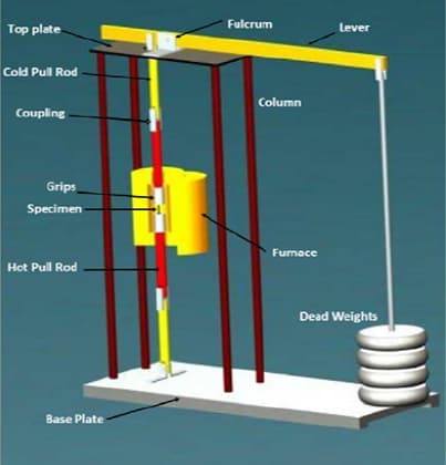
The creep test of the metals is done to foresee the metal’s behavior under high-temperature conditions. The creep test is very similar to the tensile or compression tests; however, high-temperature conditions are maintained while doing the creep test. The creep test is made by using a tensile test specimen. The starting load is determined before the initiation of the test. Thus, constant stress is applied to the metal tensile model to simulate the creep conditions. The loads can be simple weights, or a tensile test machine can maintain tension on the specimen. In addition to that, a simple furnace is placed across the specimen to create the desired elevated temperatures. A thermocouple is placed into the test specimen to control the heat of the metal. When the desired temperature is achieved, tensile or compressive stresses are applied to the test specimen. At the end of the test, the strain rate of the specimen is plotted on a graph. The results of the strain rate according to the time elapsed, is named as creep curve where considerations are done by using it. The behavior of the specimen under elevated temperature can be seen in this creep curve—the below schematic shows a typical creep curve with three distinct regions.
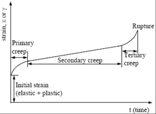
The regions on the creep curve are distinct zones where the rate of the creep differs for each zone. The derivative of the strain rate against time is called the strain rate. The fractured time of the test specimen generally depends on the amount of temperature and amount of applied stress. The initial deformation which occurs before the initiation of the test could be elastic or plastic, or both. However, even the initial plastic deformation takes place before the start of the test, the strain rate in the initial deformation cannot be stated as creep deformation. The creep test is usually taking place by applying stresses lower than the yield strength of the related material. The regions on the creep curve can be named as primary (transient) creep zone, secondary (steady-state) creep zone, and tertiary creep zone. The strain of the material initiates in the primary creep zone (aside from the initial deformation that occurs due to the loads without any heating). The strain rate of the metal reaches its minimum value in the steady-state creep zone, where the strain rate of the metal is also constant. Before the final fracture of the metal, small voids emerges in the structure of the material. These small voids grow and coalesce, so cracks occur. These cracks lead to the final failure of the metal. The importance of these small voids is actually about their emergence time. When the tertiary creep starts, these small voids arise. These small voids are distinctive patterns for failure analysis. When the microstructure of the fracture surface of a metal is observed, these small voids can be seen. The observation of the small voids indicates that half of the material’s service time is completed.
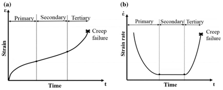
Hence, the metal part consumes half of the life-time between the steady-state creep zone and tertiary creep zone. However, the remaining life of the metal in the tertiary creep zone is not equal to half of the total life of the material. The creep rate of the material increases in the tertiary creep zone, so the progress of the creep in the tertiary area also increases in the third zone. Hence, the rest of the material’s service time is consumed more rapidly than the consumption in the steady-state creep zone. The creep rate term can be seen in the below figure. Most of the design considerations utilize the steady-state creep rate for the material that will be used in high-temperature applications. Since the creep rate is the derivative of the strain against time, the secondary creep zone performs minimum and constant creep rate at the below creep rate (strain rate) vs. time graph.
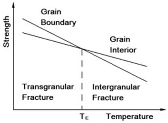
It was mentioned that the intergranular fracture mechanism is common for the creep failures. The reason for the intergranular fracture characteristic can be explained by examining the strength values of inner grains and grain boundaries at different temperatures. The tensile strength of the grain boundaries is higher than the interior of grains for low temperatures; however, the tensile strength of the interior of grains is higher than the grain boundaries for elevated temperatures. Therefore, high-temperature failures tend to occur at grain boundaries (intergranular). Since the creep takes place at elevated temperatures (for most of the metals), the intergranular characteristics of the creep fractures are commonly observed. The below schematic shows the variation of tensile stress with varying temperatures. The intersection of the intergranular and transgranular lines is called ‘equicohesive temperature’, where the strengths of both grain boundaries and inner grains are equal to each other.
The standards for creep tests are crucial to provide reliable test data. The various standards about creep testing can be seen in the below table.
Table 1. Several standards for creep
| BS 3500 | Methods for Creep and Rupture testing of Metals. |
| BS EN 10291 | Metallic Materials – Uniaxial Creep Testing in Tension. |
| BS EN ISO 899 | Plastics – Determination of Creep Behaviour. |
| ASTM E139 | Conducting Creep, Creep Rupture, and Stress Rupture Tests of Metallic Materials. |
| BS EN 1225 | Creep Factor Determination of Glass * Reinforced Thermosetting Plastics * Wet Conditions. |
| BS EN 761 | Creep Factor Determination of Glass * Reinforced Thermosetting Plastics * Dry Conditions. |
References
- Hosford, W., 2011. Materials Science. New York: Cambridge University Press.
- Effect of Microstructure and Crystallographic Texture on Mechanical Properties of Modified 9Cr-1Mo Steel – Scientific Figure on ResearchGate. Available from: https://www.researchgate.net/figure/A-typical-creep-curve-indicates-three-different-regions-the-primary-secondary-and-the_fig15_325678541 [accessed 28 Dec, 2020]
- Twi-global.com. 2020. Creep And Creep Testing. [online] Available at: <https://www.twi-global.com/technical-knowledge/job-knowledge/creep-and-creep-testing-081> [Accessed 28 December 2020].
- Dowling, N., Kampe, S. and Kral, M., n.d. Mechanical Behavior Of Materials. pp.802,809.
- Shop.bsigroup.com. 2020. Engineering Standards, Requirements For Engineering, BSI. [online] Available at: <https://shop.bsigroup.com/en/Browse-by-Sector/Engineering/?t=r> [Accessed 28 December 2020].
- Gaffard, V., Besson, J., & Gourgues-Lorenzon, A. F. (2005). Creep failure model of a tempered martensitic stainless steel integrating multiple deformation and damage mechanisms. International Journal of Fracture, 133(2), 139–166. doi:10.1007/s10704-005-2528-8
- Sasikala, G., Mathew, M. D., Bhanu Sankara Rao, K., & Mannan, S. L. (1999). Creep deformation and fracture behaviour of a nitrogen-bearing type 316 stainless steel weld metal. Journal of Nuclear Materials, 273(3), 257–264. doi:10.1016/s0022-3115(99)00057-4

