To start with, the main fracture mechanisms of the metals must be well understood for evident progress on fracture mechanics. Hence a detailed definition and comparison of ductile and brittle fracture are necessary for fundamental knowledge. It can be said that the ductile fracture of materials is mostly the desired fracture mechanism since the fracture propagation is relatively slow when compared with the brittle fracture of materials. Moreover, the plastic deformation of the material can be described as an alert for the final rupture. Nevertheless, the fracture of brittle materials hides the clues of fracture since the lack of plastic deformation during the fracture.
Ductile fracture generally occurs in a transgranular way. Just to clarify, transgranular means the propagation of fracture proceeds between grains of the material. Most of the ductile metals show necking and a certain amount of plastic deformation under a static load. These plastic deformations emerge before the final rupture of the materials. Some fundamental characteristics of ductile fracture are listed below.
- Ductile type of fraction can be identified by a certain amount of plastic change in the stress-concentrated points. This plastic deformation is observed as necking under tensile stresses.
- The rate of fracture propagation is substantially slow in the ductile type of fractures. A definite shape change or plastic deformation occurs before the rupture.
- The ductile fracture process comes with massive energy absorption. Hence, the required energy for a ductile fracture is higher than the need for a brittle fracture.
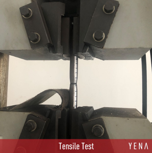
The tensile test of metal components can be an indicator for the observation of the fracture types. During the tensile testing of metals, curved edges at the necking point of the sample can be considered as a ductile fracture. A fascinating example of the ductile fracture of alloyed steel is examined by the YENA Steel Company. The failure of the alloy at the very end of the tensile test can be seen below figure.

Figure 1. The tensile test of A213-T9 alloyed steel is made by YENA Pipe. Retrieved from: (2020). Retrieved 29 October 2020, from https://yenapipe.com/alloy-steel/
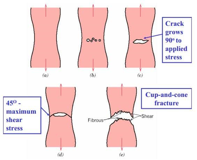
A considerable fraction of ductile failures can be observed from the shape of the fracture surfaces. A cup and cone shape can be seen for the ductile fracture of metals under tensile loads. The steps of the cup and cone fracture (ductile fracture) can be listed as; necking, the formation of small cavities, cracks formation, and cup and cone fracture (final failure).
During a simple tensile test of a metal specimen, initiation of ductile fracture starts with the appearance of microvoids. Microvoids first nucleate after grow and connects with each other. The emergence of microvoids is caused by applied stresses. The applied stresses create separations in the grain boundaries of the metal. Furthermore, interlayers between metal and impurities may also cause these separations in the structure. The steps of the ductile failure can be examined under specific subgroups.
Necking: The applied tensile force on the metal causes elastic strain in the body. The elastic strain comes with a reduction in the cross-sectional area of the metal. When the reduction in the cross-section of metal occurs, neck formation can be observed.
Formation of Small Cavities: As a result of the applied force, small voids or shelters form in the neck of the metal. The actual reason for the formation of small cavities is the separation of inclusions or other particles from the matrix of the metal. Applied tensile stress causes the separation of particles from the matrix. The formation of voids starts at where the hydrostatic tension reaches its maximum values. The peak of the pressure is usually observed at the center of the neck.
Crack Formation: The formed cavities coalescence with each other. The linking up of the cavities causes the formation of crack. The formed crack locates at the fracture surface. A newly formed crack is generally perpendicular to the direction of the applied tensile stress.
Cup and Cone Fracture: As the applied tensile force has remained on the metal, the internal crack propagates until the final failure of the edges. The failure of the edges is often caused by shear stresses. The shear of the edges is also occurred by the formation and growth of the microvoids. This total failure of the metal part is called the cup and cone fracture because of the shape of the fracture surfaces. The direction of the shear generally makes an angle of 45°with the applied stress (The reason for the 45° is sourced from Schmidt’s Law).
The importance of the inclusions or impurities for the ductile fracture must be stated for deep learning of the fracture concept. The formation of the microvoids starts at the points where inclusions located. The reason for that is the mechanical weakness caused by impurities. The regions where inclusions locate is relatively weaker than the remaining areas. Hence, the ductile behavior of the material is strongly dependent on the number or rate of the impurities.

Figure 2. Steps of cup and cone fracture. Retrieved from: Paul, A. (2020). Ductile Fracture of Metals by Necking – Cup and Cone Failure | CivilDigital |. Retrieved October 2020, from https://civildigital.com/ductile-fracture-metals-necking-cup-cone-failure/
A piece of brief information about the examination of fracture surfaces can be useful. In order to examine the fracture surfaces in detail, scanning electron microscopes are utilized. The detailed investigation on fracture surfaces is called ‘fractographic studies.’ The selection of the scanning electron microscope during the examination of the fracture surfaces have two certain benefits.
SEM provides a better resolution than optical microscopes and also ensures a higher depth of field. These features of SEM is necessary for the analysis of the topography of fracture surfaces. Under high magnifications of SEM, ductile fractured surfaces are observed as dimples. The dimples in the fracture surfaces are mostly caused by the formation and coalescence of microvoids. At the center of the necking, the microvoids link up in a flat direction. Nevertheless, the edges of the fracture regions are generally oval-shaped since the shear stresses are the reason for the fracture at the edges.

Another essential type of fracture is called brittle fracture. Brittle type of fracture is mostly observed in high-strength metals and ceramics. Moreover, ductile metals may fail in a brittle manner in low operational temperatures. The strain rate of the fractured material is generally lower than 5 % in brittle fracture cases. Hence the brittle failure of the metals occurs typically without any plastic deformation. The propagation of the cracks in the brittle materials is faster than the ductile materials. The direction of the cracks is mostly perpendicular to the direction of applied stress. Thus, a flat fracture surface can be examined after the tensile testing of a brittle metal.
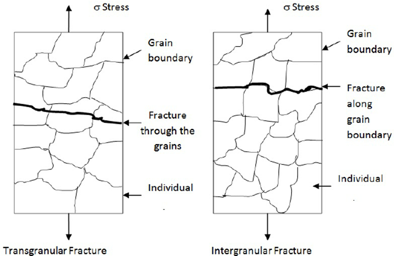
The surfaces of the brittle fractured metals can be identified from the V-shaped traces. Neighboring regions to the center of fracture exhibit these V-shaped traces, which are also known as ‘chevrons.’ Most of the brittle fractures in a metal body are caused by the continuous breaking of the interatomic bonds in the structure. The failure of the interatomic bonds aligns in the same crystallographic planes, and this phenomenon is termed as ‘cleavage.’ Moreover, the cleavage failure of the atomic bonds is also known as transgranular since the propagation of the fracture proceeds on the grains of the material. In small magnifications, transgranular fracture surfaces are observed in granulous shapes just because of the fracture mechanism of the brittle material.
The brittle failure of the materials may propagate along the grain boundaries. The propagation of the cracks along the grain boundaries is called as ‘intergranular’ failure. The intergranular fracture of the brittle materials is mostly examined in the structures where segregation or precipitations located at the grain boundaries. For steels, hypereutectoid structures are risky in the manner of intergranular fracture since the possible precipitation of the cementite on the grain boundaries may create a brittle network in the steel.

Figure 4. Transgranular and intergranular fracture. Retrieved from: Ghiasi, Vahed & Omar, Husaini & Mdyusoff, Zainuddin & Yusoff, Bujang & Huat, Ratnasamy & Muniandy, Ratnasamy & Mohd, Naza & Alias,. (2010). A New Model of Microcracks Propagation in Granite Rock. Australian Journal of Basic and Applied Sciences. 4.
Read more: Introduction to Fracture Types
For further information please read: Ductile-Brittle Transition Temperature and Impact Energy Tests
Bibliography
- Askeland, D., Haddleton, F., & Green, P. (2013). Science and Engineering of Materials (pp.780, 786). Boston: Springer US.
- Material, E. (2020). Explain the mechanism of fatigue failure in ductile and brittle material. Retrieved October 2020, from https://www.ques10.com/p/21890/explain-mechanism-of-fatigue-failure-in-ductile-an/
- Yang, W.-J., Yu, C.-T., & Kobayashi, A. S. (1991). SEM Quantification of Transgranular vs Intergranular Fracture. Journal of the American Ceramic Society, 74(2), 290–295. doi:10.1111/j.1151-2916.1991.tb06877.x
- Callister, W. (2001). Fundamentals of materials science and engineering (pp. 208-210). New York: Wiley.
- Chauhan, Ankur. (2018). Deformation and damage mechanisms of ODS steels under high-temperature cyclic loading. 10.5445/IR/1000080339.


